Difference between revisions of "Moving A CAD file into a New Reference System"
(Created page with "Moving a CAD model into a new reference system means to change the internal coordinate system of the model from the one decided by the Cad designed, into a new one which suit...") |
|||
| (2 intermediate revisions by one other user not shown) | |||
| Line 1: | Line 1: | ||
| + | [[it:Cambiare il Riferimento ad In Modello CAD]] | ||
| + | [[File:Transformation.png|thumb|right|400px|Transformation Menu]] | ||
| + | |||
| + | == Introduction == | ||
Moving a CAD model into a new reference system means to change the internal coordinate system of the model from the one decided by the Cad designed, into a new one which suit the need of the inspection.<br /> | Moving a CAD model into a new reference system means to change the internal coordinate system of the model from the one decided by the Cad designed, into a new one which suit the need of the inspection.<br /> | ||
| − | Even if it is possible and easier to create a reference system as per the Cad model and then change the coordinate system in ARCO after the synchronization, in certain | + | Even if it is possible and easier to create a reference system as per the Cad model, and then change the coordinate system in ARCO after the synchronization, in certain cases, it is preferred to change directly the model internal reference system.<br /> |
<br /> | <br /> | ||
| − | The procedure the change a reference system | + | == Pre-requisites == |
| + | The procedure the change a reference system of a CAD require some care and the basic steps are as follow: | ||
#[[Importing a CAD Model|Import the CAD file]] | #[[Importing a CAD Model|Import the CAD file]] | ||
#Make sure that the current reference system is MAC | #Make sure that the current reference system is MAC | ||
#Make sure model in [[Synchronize the Model to MAC refence system|synchronized to machine reference system]] | #Make sure model in [[Synchronize the Model to MAC refence system|synchronized to machine reference system]] | ||
| − | #Click on | + | #Make active the [[Cad View|CAD View]] |
| − | Make | + | #Click on ''Modify - Transformation'' |
| − | In order to rotate a model, | + | <br /> |
| − | Select the Rotation about the axis | + | <br /> |
| − | Type the angle for rotation | + | The first operation to be done is to fix the orientation of the model even if the origins are not being set yet, after that it will be fixed the origin and then, the last changes are symmetry and scaled.<br /> |
| − | + | If some of the described steps are not required, then just skip to the next one.<br /> | |
| − | Click append | + | |
| − | Click Apply | + | == General Consideration == |
| − | Confirm that | + | [[File:Make Acopy.png|thumb|right|200px|Transformation Menu]] |
| − | + | The model is moving and not the reference system! <br /> | |
| − | + | If, when the transformation dialog is open, some part of the model is selected, then that part will be changed, if none of the part is selected then the whole model will be modified.<br /> | |
| − | In order to move the model to a new origin, | + | if the Check box "Make A copy" is set, then the original model will not be deleted otherwise the modified model will substitute the original |
| − | Select the Translation from the list | + | |
| − | Type the value for each axis to be moved | + | |
| − | + | == Changing the Orientation == | |
| − | Click append | + | In order to rotate a model, the procedure is as follow: |
| − | Click Apply | + | #Select the Rotation about the axis the model needs to rotate |
| − | Confirm that | + | #Type the angle for rotation |
| − | + | #Click append | |
| − | + | #Click Apply | |
| − | + | #Confirm that the rotation is to be applied to the whole model if no selectin was done. | |
| − | + | ||
| − | + | == Changing the Orientation == | |
| − | + | In order to move the model to a new origin,, the procedure is as follow: | |
| + | #Select the Translation from the list | ||
| + | #Type the value for each axis to be moved | ||
| + | #Click append | ||
| + | #Click Apply | ||
| + | #Confirm that the rotation is to be applied to the whole model if no selectin was done. | ||
| + | |||
| + | |||
| + | == Making a Symmetry == | ||
| + | In order to create symmetrical definition of the model, the procedure is as follow: | ||
| + | #Select the Symmetry plane required for the symmetry from the list | ||
| + | #Click append | ||
| + | #Click Apply | ||
| + | #Confirm that the rotation is to be applied to the whole model if no selectin was done. | ||
| + | |||
| + | == Changing the Scale of a Model == | ||
| + | In order to scale a model, the procedure is as follow: | ||
| + | #Select the Scale from the list | ||
| + | #Type the scale factor for each axis | ||
| + | #Click append | ||
| + | #Click Apply | ||
| + | #Confirm that the rotation is to be applied to the whole model if no selectin was done. | ||
| + | |||
| + | |||
| + | <gallery widths=150px heights=150px caption="Transformation Dialogs"> | ||
| + | File:Rotation.png|Rotation from list | ||
| + | File:Translation.png|Translation from list | ||
| + | File:Symmetry.png|Symmetry from list | ||
| + | File:Scale.png|Scale from list | ||
| + | File:Rotation Dialog.png|Rotation Dialog | ||
| + | File:TRanslatin Dialog.png|Translation Dialog | ||
| + | File:Scale Dialog.png|Scale Dialog | ||
| + | File:Simmetry Dialog.png|Symmetry Dialog | ||
| + | </gallery> | ||
| + | |||
| + | [[it:Spostare un file CAD in un nuovo sistema di riferimento]] | ||
| + | [[zh-cn:将CAD文件移动到新的参考系统中]] | ||
| + | [[pt:Movendo um arquivo CAD para um novo sistema de referência]] | ||
| + | [[de:Verschieben einer CAD-Datei in ein neues Referenzsystem]] | ||
| + | [[es:Mover un archivo CAD a un nuevo sistema de referencia]] | ||
| + | [[en:Moving A CAD file into a New Reference System]] | ||
| + | |||
| + | [[Category:Help_On_Line]] | ||
Latest revision as of 13:14, 12 June 2018
Contents
Introduction
Moving a CAD model into a new reference system means to change the internal coordinate system of the model from the one decided by the Cad designed, into a new one which suit the need of the inspection.
Even if it is possible and easier to create a reference system as per the Cad model, and then change the coordinate system in ARCO after the synchronization, in certain cases, it is preferred to change directly the model internal reference system.
Pre-requisites
The procedure the change a reference system of a CAD require some care and the basic steps are as follow:
- Import the CAD file
- Make sure that the current reference system is MAC
- Make sure model in synchronized to machine reference system
- Make active the CAD View
- Click on Modify - Transformation
The first operation to be done is to fix the orientation of the model even if the origins are not being set yet, after that it will be fixed the origin and then, the last changes are symmetry and scaled.
If some of the described steps are not required, then just skip to the next one.
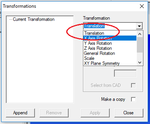
General Consideration

The model is moving and not the reference system!
If, when the transformation dialog is open, some part of the model is selected, then that part will be changed, if none of the part is selected then the whole model will be modified.
if the Check box "Make A copy" is set, then the original model will not be deleted otherwise the modified model will substitute the original
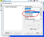
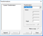
Changing the Orientation
In order to rotate a model, the procedure is as follow:
- Select the Rotation about the axis the model needs to rotate
- Type the angle for rotation
- Click append
- Click Apply
- Confirm that the rotation is to be applied to the whole model if no selectin was done.
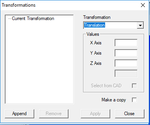
Changing the Orientation
In order to move the model to a new origin,, the procedure is as follow:
- Select the Translation from the list
- Type the value for each axis to be moved
- Click append
- Click Apply
- Confirm that the rotation is to be applied to the whole model if no selectin was done.
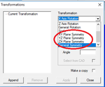
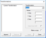
Making a Symmetry
In order to create symmetrical definition of the model, the procedure is as follow:
- Select the Symmetry plane required for the symmetry from the list
- Click append
- Click Apply
- Confirm that the rotation is to be applied to the whole model if no selectin was done.
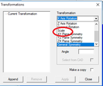
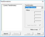
Changing the Scale of a Model
In order to scale a model, the procedure is as follow:
- Select the Scale from the list
- Type the scale factor for each axis
- Click append
- Click Apply
- Confirm that the rotation is to be applied to the whole model if no selectin was done.
- Transformation Dialogs
Rotation from list
Translation from list
Symmetry from list
Scale from list
Rotation Dialog
Translation Dialog
Scale Dialog
Symmetry Dialog


