Custom Tolerance for 3D Point Deviation

From version 3.6 has been implemented non standard profile tolerance for GSURF, CURVE and POINT features.
The difference from the ANSI is that, using the 3D profile, the deviation is calculate along the 3D vector that joint the measure point and the nominal, while, in the standard , the deviation is along the normal direction of the nominal point.
Although not in the ANSI standard this tolerance is quite common in the automotive industry.
The different methods can be called from the PROFILE of POINT/SURFACE/CURVE tolerance panel.
The DMIS code created in the two cases is as follow:
F(POINT_PROFILE_ANSI)=FEAT/POINT,CART,0.0000,0.0000,0.0000,0.00000000,0.00000000,1.00000000

F(POINT_PROFILE_3D)=FEAT/POINT,CART,0.0000,0.0000,0.0000,0.00000000,0.00000000,1.00000000

FA(POINT_PROFILE_ANSI)=FEAT/POINT,CART,0.10000,0.20000,0.30000,0.00000000,0.00000000,1.00000000

FA(POINT_PROFILE_3D)=FEAT/POINT,CART,0.10000,0.20000,0.3000,0.00000000,0.00000000,1.00000000


V(TEXT)=VFORM/ALL

DISPLY/TERM,V(TEXT)

TEXT/OUTFIL,'This is the Standard ANSI profile Tolerance'

T(ANSI_PROFILE)=TOL/PROFS,-0.1000,0.1000

OUTPUT/FA(POINT_PROFILE_ANSI),TA(ANSI_PROFILE)


TEXT/OUTFIL,'This is the NON Standard 3D Profile Tolerance'

T(3D_PROFILE)=TOL/USETOL,'PROFS_3D',-0.1000,0.1000

OUTPUT/FA(POINT_PROFILE_ANSI),TA(3D_PROFILE)

DISPLY/OFF
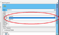
Selection of the different methods of profile tolerance
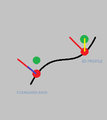
Difference between ANSI and 3d profile

Features whom the tolerance is applied
